Overview
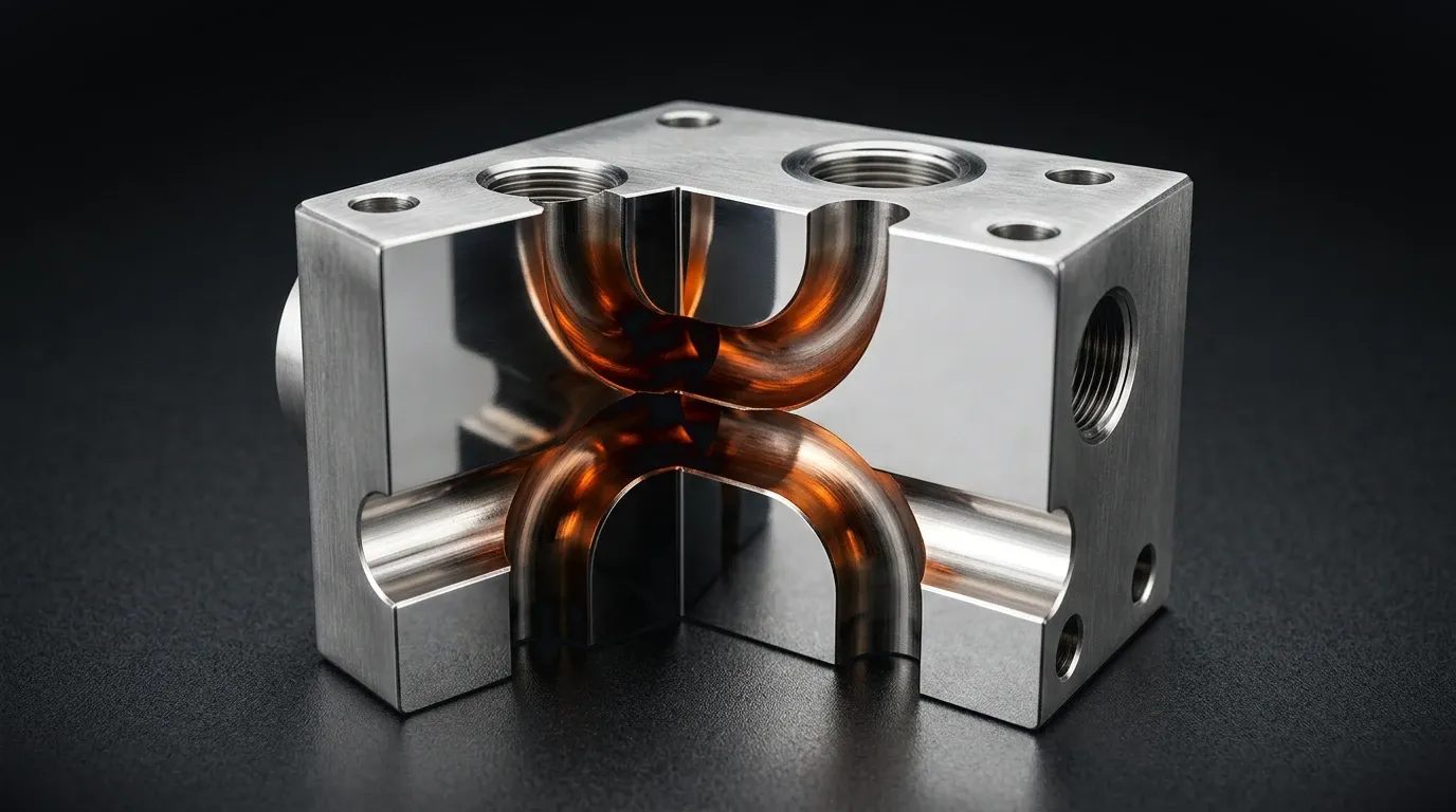
Multi-material metal parts place up to three alloys in one geometry, putting each alloy where its properties matter most. Copper can carry heat, stainless steel can provide corrosion resistance, and nickel or titanium can address temperature or mass constraints. Good bimetallic part design starts with explicit CAD bodies, controlled transitions, and a load-case review.
Why use multiple alloys in one part?
Multi-material metal parts make sense when one alloy cannot meet every requirement in the same location. A copper region may need high thermal or electrical conductivity, while an austenitic stainless region may need corrosion resistance and stable dimensions. Alloy 718 can support demanding temperature and strength requirements, while Ti-6Al-4V can reduce mass where stiffness and density matter.
Assign each alloy to a defined function instead of treating the material boundary as an afterthought. Put the conductive region near the heat path, the wear or corrosion-resistant region at the exposed surface, and the stronger alloy around concentrated loads when the geometry supports that choice. A clear division can reduce separate component count, simplify the surrounding design, and keep critical features tied to the alloy best suited to them.
Multi-material design still needs a complete load path. Review force, temperature, pressure, fluid exposure, electrical requirements, and service life together. A pairing that looks sensible for heat transfer may need a different transition location when the part sees repeated temperature changes or a high bending load.
How should CAD represent a multi-material part?
CAD setup should make alloy ownership unambiguous. Create one body per alloy, and name every body with the alloy family and grade, such as Copper_CuCrZr, Stainless_316L, or Nickel_Alloy718. Use names that survive handoff to procurement, inspection, and revision control. Do not rely on display color alone.
A STEP or 3MF multi-body file is the clearest starting point when the CAD system preserves body names and shared coordinates. Separate STL files also work: provide one STL per body, keep every file in the same coordinate system, and use matching names that identify the alloy. A single STL cannot reliably communicate separate alloy regions unless the receiving workflow has another explicit material map.
Before review, check that bodies touch where intended, do not overlap accidentally, and do not leave an unintended gap. Define the interface with enough surrounding geometry for inspection and dimension review. Add material notes to the drawing or design record, including grade, condition if relevant, and which dimensions belong to which body. Mesh2Metal analyzes CAD in the browser, so you can check the geometry before requesting an instant manufacturability verdict.
How should transition zones support bimetallic part design?
Transition zones should change gradually where the load allows it. A gradual boundary gives the design more room to manage differences in stiffness, conductivity, and thermal movement. Avoid placing a sharp material change at a notch, thin corner, small hole, seal land, or other stress-sensitive detail.
Keep critical machined features within one alloy whenever practical. Datums, bearing seats, precision bores, sealing surfaces, threads, and tightly controlled mounting faces are easier to specify and inspect when each feature stays inside a single material region. If a feature must cross an interface, call out the boundary location, the controlling dimensions, and the required inspection evidence.
Place the transition away from the most demanding local feature, then give the interface enough area for the expected load path. Rounded changes and generous local thickness can help, but geometry alone does not settle the design. Review the interface against the actual temperature range and load case, then link the result to the manufacturability review.
How does thermal expansion affect a multi-material part?
Thermal expansion is a first-order check for every multi-material design. Typical linear coefficients of thermal expansion are approximately:
| Material | Typical CTE |
|---|---|
| Copper | ~17 µm/m·K |
| Austenitic stainless steel | ~16–17 µm/m·K |
| Alloy 718 | ~13 µm/m·K |
| Ti-6Al-4V | ~8.6 µm/m·K |
A larger CTE difference creates more relative movement as part length and temperature change increase. Copper and austenitic stainless steel have similar typical values, so copper steel part design may have a smaller expansion mismatch than a copper-to-titanium pairing. Alloy 718 sits between the listed extremes. Ti-6Al-4V can create a more significant relative movement against copper or austenitic stainless steel.
Check the cold and hot dimensional conditions, not only the room-temperature CAD. Identify whether the interface is restrained, whether a machined feature must remain aligned, and whether an attached seal or bearing can tolerate the movement. Include thermal properties in the design record and request them in the quality certificate when they matter to acceptance.
Which alloy pairings are worth considering?
The table below gives starting points for common property splits. Confirm for your load case.
| Pairing | Why consider it | Design attention |
|---|---|---|
| Copper + austenitic stainless steel | Heat or electrical path with corrosion resistance | Check temperature cycling and interface dimensions |
| Copper + Alloy 718 | Conductive region with high-temperature strength | Check CTE difference and the load path |
| Copper + Ti-6Al-4V | Conductive region with lower mass | Check expansion mismatch and local restraint |
| Alloy 718 + Ti-6Al-4V | High-temperature capability with lower mass | Check stiffness, temperature, and feature placement |
| Stainless steel + Ti-6Al-4V | Corrosion resistance with lower mass | Check the interface under combined loads |
These pairings are not a substitute for a material specification. Confirm chemical, mechanical, thermal, and dimensional requirements for the application. The multi-material overview and material pages can help narrow the starting set.
What should the design review verify?
Design review should verify five items before the geometry moves to a quote:
- Body identity: every body has one alloy, a useful name, and a clear boundary.
- Geometry: bodies share the intended coordinates, touch correctly, and leave room for inspection.
- Feature ownership: critical machined features stay in one alloy where practical, with datums and tolerances assigned clearly.
- Thermal behavior: CTE values, temperature range, restraint, and dimensional acceptance are documented.
- Evidence: the requested quality certificate identifies material results, dimensional deviation, mechanical and thermal properties, traceability, and interface inspection.
Drop your CAD files into the browser for a local geometry check, then use the instant quote flow when the material map is ready. If the design needs a change, the manufacturability verdict should state what to change and why. A disciplined material map makes the review faster, gives procurement a clear specification, and keeps the final part aligned with the engineering intent.
Questions
How many alloys can one part include?
Mesh2Metal supports up to three alloys in one part. Identify every alloy region clearly in the CAD model before review.
Can I specify a copper and stainless steel part?
Yes. Copper and stainless steel can be evaluated as a multi-material pairing, subject to geometry, loads, temperature, and the requested certificate.
Which file formats support multiple bodies?
STEP and 3MF can carry multi-body information. Separate STL files can also represent the bodies when each file is named and located clearly.
What does the quality certificate cover?
The quality certificate includes material, dimensional, mechanical, thermal, traceability, and conformance information. Ask for interface inspection to be identified for the part.
Sources (4)
- [1] Copper , Wikipedia
- [2] Stainless steel , Wikipedia
- [3] Ti-6Al-4V , Wikipedia
- [4] Certificate of conformance , Wikipedia